For almost 40 years, Cannon Boiler Works has been committed to helping produce energy in the most efficient manner possible. As a forward-thinking leader in the efficiency of industrial energy, CBW products reduce fuel costs and the emission of greenhouse gasses.
CBW designs, manufactures, and services boilers and pressure vessels as well as an extensive line of additional products. The company offers feed water heaters, condensing economizers, heavy duty economizers, vent condensers, steam accumulators, and custom heat exchangers, as well as waste heat boilers, finned tubing products, inter- and after-coolers, lube oil coolers, air coolers, and other specialty products.
Problem
CBW provides a wide variety of heat exchangers, both new and rebuilt. The company’s experience has helped their customers solve many difficult corrosion problems by using sophisticated material selection and creative design features that greatly improve the performance and longevity of these exchangers.
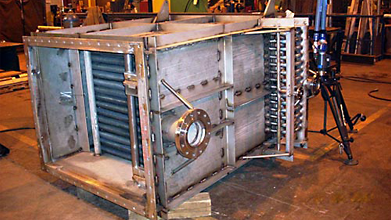
One product, large air-cooled, high-temperature heat exchangers that are the subject of this case study are produced in three sizes: what CBW calls a 300 size which is 25” x 25” x 54”, a 1500 size which is 49” x 80” x 79”, and a 3000 size which is 87” x 100” x 109”. To properly inspect the 300, there are approximately 62 different features and 80 constructions that must be measured. The 1500 raises these numbers to 150 features and 280 constructions while the 3000 raises them even higher to 200 features and 290 constructions.
These exchangers have structural bolting flanges on the shell side and finned tubes with pipe headers on the tube side. CBW must measure and report the tube side flanges relative to the centers of the structural flange bolt hole patterns. They must also report the integrity of the structural flange bolt hole patterns themselves as they tend to distort after welding.
To get these measurements, CBW would use a combination of levels, plumb bobs, tape measures, straight edges, and a geometry-based metrology. By virtue of the construction of these units, there were many features that could not be measured using analog methods like these. Once completed, the largest unit weighs nearly eight tons and the shell-side passage is completely blocked with a finned tube array. This means that once completed, the only access to the bottom from the top is around the side of the unit.
Imagine that the perimeter of the top of the unit is a rectangular bolting flange with 48 holes and the bottom is a bolting flange with 52 holes. These patterns must be measured and each hole located to within 3/32”. Then the bolting pattern centers must be located within 1/4” of one another in two dimensions.
The analog methods of measuring were a mixture of not capable, not accurate enough, too complicated, and had the potential for human error with the manual reporting required. These tools and methods also introduced many variables that could alter measurement accuracy.
For example, when CBW tried to find if a connection was centered between two rows of bolt hole centers 100 inches apart, they first had to “fit” the rows to separate lines and measure toward the connection perpendicular to one of those lines. It is difficult to find a flanged connection center (center of an ANSI flange bolt pattern) and then to determine if this center is midway between the bolt hole rows within the required 1/8”. This required analog reconciliation of potential variances in the bolt hole rows, the bolt hole diameters, and the flanged connection manufactured tolerances. It was basically trying to measure between two imaginary points that result from a best fit of 4 to 28 features within that 1/8” over a distance of 50 inches. This proved VERY difficult, if not impossible, using traditional, analog tools and methods.
Solution
As a solution to the measurement deficiencies of more traditional tools, CBW turned to FARO. With FARO’s presence in the portable CMM market, the quality of its hardware and software, and its excellent customer support, the overall value FARO represented to CBW was clear when the company considered these factors relative to competing companies and products.
Until the purchase and implementation of a FaroArm and CAM2 software, there were a number of features that were requested by customers for measurement that simply were not possible using analog tools and methods. In the example of the fabricated bolting flange patterns that are measured relative to the pattern center as well as other features relative to this same center, the FaroArm made it possible to measure and report these and other features. The CAM2 software and its iterative capabilities provided CBW the insight into fabrication methods and sequences that helped them eliminate unit-to-unit variances in manufacturing. This yielded a more consistent and precise product. The type of depth in quality the FARO system offered cemented the end customer’s confidence in CBW’s product.
It’s an interesting application in that CBW calculates imaginary (non-measureable) center points of a rectangular bolt hole pattern and reports the centers of pipe header outlets relative to those points. The software must also perform an iterative fit of these structural flange bolt hole patterns and report any holes that fall out of “tolerance” in order to give a “real world” bolt-up acceptance or rejection. In this particular application, it’s sort of like an advanced go-no go gauge on steroids. What makes all of this especially interesting is that this is done with five device positions while holding 1/8” tolerance on a fully welded assembly with many feet of weld between measured features.
Because of the blocked shell-side passage on the heat exchangers, a number of device moves (leapfrogs) must be performed to construct each flange from data taken in four different positions. Leapfrogging is a technique used with portable measuring devices like the FaroArm that extends their working volume by measuring reference points in one position and again after moving the device to a new position. The reference points link to the new device position, allowing for measurements to be taken and reported in the same reference frame.
The level of measurement that CBW was looking for, up to five device positions with so many features and constructions, initially took some time and a healthy dose of help from FARO customer service to develop. Applications Engineer Todd Wilson helped to develop a core programming and methodology for a single product size. Once the alpha version was reached and consistency in measurement was established, it took as little as a half a day to train additional operators on how to use the FARO system with the alpha programming. Once the beta version of this programming was complete, implementing an inspection process and optimizing the software to achieve their goals of adding features, constructions, coordinate systems, multiple alignments, and corresponding reports was a matter of specifying the setup to the shop and providing the time to perform the measurements.
Originally though, the programming had one coordinate system alignment based on part features that was used only to measure the final product. Since that first program, CBW has integrated two more iterative alignments used to report large bolt patterns of 48 or more holes and their conformance to tolerance independent of other unit features. The programming uses a portion of the measurements for one alignment, generates a report, uses a new set of features for another alignment, generates a report, and finally the last alignment with a third and final (overall) report.
From that original starting point, and after advanced training from FARO, CBW added measured features to the final measurement program as well as a number of in-process measurements. The result was a robust quality system for their primary products using the FaroArm and CAM2 software. More specifically, this system has grown from the one “seed” program of one measurement of one product size to over ten programs spanning three product sizes. Even the CAM2 software’s ability to output raw data has become an integral component of the quality system for these products with respect to 3rd party data analysis.
The primary parts mentioned here are so large and difficult to measure using analog methods that once confidence in the new FARO system was established, the technology was quickly accepted by everyone from welders/fabricators on up to the president of the company. The confidence in the methods and technology took approximately nine months to develop, but once it was reached CBW found themselves leaning on the FARO system more and more in daily operation.
There are two core components of the final product that are measured after they are produced, but before they are used in unit fabrication. CBW also uses the FaroArm during assembly to ensure that the key connections are located within tolerance before they are locked into place. Then, of course, there is a final measurement of the finished product. In general, there are four FaroArm measurements and reports that are analyzed during the construction of the two larger-sized primary products detailed earlier.
This range of products is an example of the unique work done by CBW and presented a unique measurement challenge for the FARO system. That’s to say, the designs of each size are property of CBW, but by the nature of their application are developed in conjunction with the end customer. Products this large and having so many features require several device moves. Both the final product tolerances and those applied at the in-process inspection points are so tight that sometimes alternative alignments must be used to check for real-world conformance. Plainly, sometimes CBW must simply check to see if a particular unit will fit into the assembly. To do this, they have the programming perform iterative alignments over varying geometries ranging from single bolt hole patterns of 52 holes in a single plane to 2 bolt hole patterns of 12 holes each and 7 different connection points.
In addition, CBW has qualified several shop fixtures using FARO and is in the process of designing more elaborate fixturing for production that will also be qualified as accurate build tools using FARO.
Return on Investment
Over the last three years, approximately 37 units have been built and measured using the FARO system. In this time, the measurement procedure has increased in depth from just a final measurement of a finished unit to preliminary measurements and measurement of individual fabricated components before assembly even begins. For each, FARO has been successfully used.
“We have been able to reduce the variance of in-process placement of key features from as much as 7/16” to 1/8” from one unit to the next,” said Marc Dinsmore, Mechanical Design Engineer at CBW. “The FARO system has allowed us to become so consistent and accurate from build to build that the largest cause of variance between builds has become the actual mill tolerances on the raw material being used!”
As another benefit, there have been several instances for CBW where the FARO system has proven to be a valuable tool for reverse engineering during exchanger rebuilds and boiler re-tube contracts. These types of jobs require careful measuring of corroded or incomplete components with many mating surfaces. Accurate measurement is vital to the success of these jobs and the FARO system ensured near perfect replacement parts by virtue of its accuracy and its robust data collection. These jobs were previously completed without the FARO system, but not with the confidence and streamlined efficiency that system affords more difficult jobs.
The CAM2 software’s ability to preserve data for documentation and future analysis has also proven to be very valuable. Going back into previous builds has allowed CBW to see the improvement in their processes and will prove more and more valuable as additional data is extracted.
Though it is difficult to always quantify a dollar amount on savings and, in this case, using the FARO system actually added some time to the build process, CBW is more interested in the end result. That end result is the assurance of accurately placed features and that is the ultimate goal. That assurance was not there using analog methods. Without FARO, the inspection could not be completed in the desired detail and that should always be the goal of any quality process.
For CBW, there is an overall savings in the development of their quality system centered on FARO. Their FARO system has eliminated much of the costly rework at the end of the build through in-process inspections with the FaroArm. The results of some early inspections led to fabrication process changes that eliminated much of the weld distortion that was found. Those early results also yielded design changes along with fixturing and bracing to replace the older analog (tape measure) placement methods that had created product variance and non-conformance. These improvements shed an estimated 8 to 24 man hours from the finished product fabrication time.
“Having just scratched the surface of the FARO system’s value in our company,” said Mr. Dinsmore. “I can easily say that several key benefits we’ve experienced have been reduced work, shortened build times, improved build quality and consistency, improved insight to some of our standard procedures, and confidence in many replacement and/or repair contracts.”
“I must tell you,” Mr. Dinsmore concluded, “that I have great faith in our FARO Fusion and the customer service we have received in the past couple of years!”