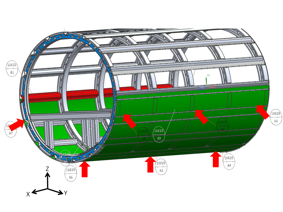
Figure 1. Primary datum (in green) defined by nine datum target areas (A1 to A9 – 2 datum target areas not shown)
This post will present a possible case in the aerospace industry for locating a fuselage part with 9-2-1 location, using datum target areas. For more detailed information on datum targets, you may refer to the ASME standard, section 4.24 [1].
N-2-1 Location with Datum Target Areas
In a previous post, we talked about using 3-2-1 precision location to create an accurate and repeatable datum reference frame for the part, while avoiding overconstraint. However, for most sheet metal manufacturing processes, the main dimensional problem is the sheet metal deformation normal to the surface [2]. This deformation cannot be neglected, even under the self-weight of the workpiece. Analysis shows that the average deflection of a sheet steel plate 400 mm x 400 mm x 1 mm under its self-weight can be between 1-3 mm with a 3-2-1 location layout. Therefore, an adequate fixturing system for sheet metal usually requires N>3 locators on the primary datum to properly restrain workpiece deformation.
9 Datum Target Areas on the Primary Datum Plane
For our case, we selected 9 positions for datum targets on the largest cylindrical surface of the fuselage (Figure 1). Since we have a very large surface, the use of datum target areas, as opposed to datum target points, makes it easier to measure. In our case, these datum target areas are designated by A1 to A9.
The directions of the axes can be defined as:
- X-axis: Along the longest axis of the fuselag
- Y-axis: Perpendicular to the X-axis, along the plane of the fuselage passenger floor
- Z-axis: Perpendicular to both the X- and Y-axes, directed toward the ceiling
With these nine datum target areas, we have eliminated translations in the Z- and the Y- axes, and rotation around the Y-axis (pitch) and Z-axis (yaw).
2 Datum Target Areas on the Secondary Datum Plane
We selected 2 points on the second largest surface of the part, perpendicular to the primary datum (Figure 2). Again, we have made use of datum target areas instead of points for our simulated datum. These datum target areas are designated by B1 and B2.
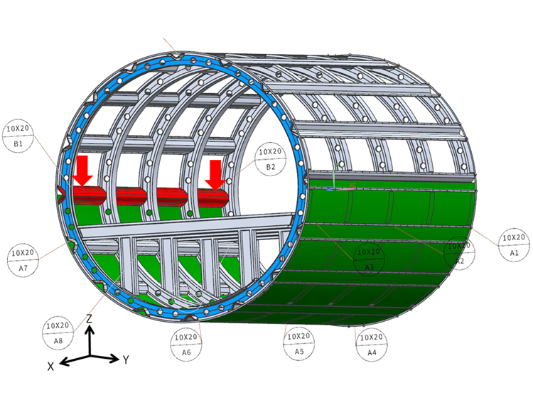
Figure 2. Secondary datum (in red) defined by two datum target areas (B1,B2)
With these two datum target areas, we have eliminated the rotation around the X-axis (roll); that is the rotation around the longest axis of the fuselage.
1 Datum Target Area on the Tertiary Datum Plane
We selected 1 datum target area on a surface perpendicular to both of the previous datums (Figure 3). This datum target area is designated by C1.
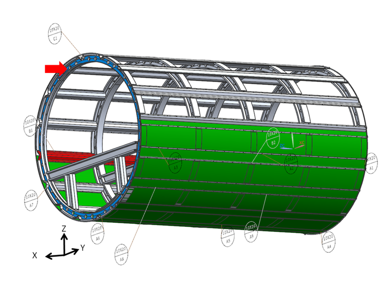
Figure 3. Tertiary datum defined by one target area (C1)
With this final datum target area, we have eliminated the translation in the X-axis, that is along the longest axis of the fuselage.
We should emphasize the fact that we could have put more than nine targets on the primary datum in different positions; the number and position of locators are usually determined using finite element analysis [3]. In upcoming posts, we will delve into the various cases with measured data to observe these effects.
References
- ASME Y 14.5-2009, Dimensioning and Tolerancing. New York: American Society of Mechanical Engineers.
- Cai WW, Hu SJ, Yuan JX. Deformable Sheet Metal Fixturing: Principles, Algorithms, and Simulations. ASME. J. Manuf. Sci. Eng. 1996;118(3):318-324. doi:10.1115/1.2831031.
- A location optimization method for aircraft weakly-rigid structures, Zhong-Qi Wang, Yuan Yang, Yong-Gang KangZhong-Qi Wang, Yuan Yang, Yong-Gang Kang and Zheng-Ping Chang ,Int. J. Simul. Multisci. Des. Optim., 5 (2014) A18 ,DOI: