In a previous post, we elaborated on the principles of precision location and presented one of the techniques for achieving it: The use of slots. However, with slots, we can still have the problem of high manufacturing cost if the part has substantial thickness. This is because manufacturing a slot is simply more complex than drilling a hole, in relatively thick parts. One technique to have the best of both worlds is to use diamond pins.
Precision location in machining and assembly is of paramount importance to position parts and avoid overconstraint. With a proper number of constraints, we would ideally determine the location of our part and obtain negligible stress. This point was made clear nearly one and a half centuries ago by James Maxwell [1]:
Hence if a solid piece is constrained in more than six ways it will be subject to internal stress and will become stressed and distorted, and this in a manner which, without the most exact micrometrical measurements, it would be impossible to specify. In apparatus for accurate work, it is essential that the bearings for every piece should be properly defined, both in number and position.
Use of Diamond Pins
Diamond pins are used to overcome overconstraint problems while keeping manufacturing costs low. A diamond shaped pin controls the dimension aligned with its widest axis precisely while allowing larger variation in the other axis (Figure 1). Information on diamond pins and their use can be obtained through various manufacturers [2].
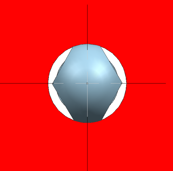
Figure 1. Diamond Pin.
Next, we apply the geometric dimensioning and tolerancing principles defined by the ASME standard [3] to a part designed for diamond pin application:

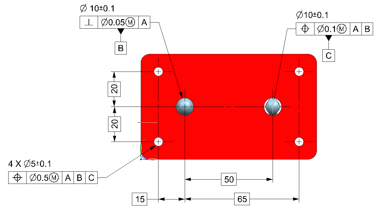
Figure 2. Part designed for diamond pin application with tolerances applied (Primary datum feature (A): The flat plane at the bottom – Not Shown)
In Figure 2, we can observe the following:
- Primary datum feature (A): The flat plane at the bottom of the workpiece (Not shown).
- Secondary datum feature (B): The hole defined with a feature size tolerance of ±0.1 mm and a perpendicularity tolerance of 0.05 um with respect to datum feature A.Tertiary datum feature (C): The hole with a feature size tolerance of ±0.1 mm and a position tolerance of 0.1 um with respect to datum reference frame AB.
- The 4 hole pattern: The holes in the pattern have a feature size tolerance of ±0.1 mm and a position tolerance of 0.5 mm at MMC with respect to datum reference frame ABC. The position of these holes is defined with basic dimensions with respect to the datum reference frame ABC.
Lastly, it must be stated that diamond pin applications are particularly useful if your part has an important thickness and must be machined by a milling machine. For sheet metal parts manufactured with stamping processes, the use of slots can be a better solution.
References
- Maxwell, James Clerk. “General considerations concerning Scientific Apparatus”, The Scientific Papers of James Clerk Maxwell. Ed.W. D. Niven.. 1st ed. Vol. 2. Cambridge: Cambridge University Press, 2011. 505-522. Cambridge Library Collection. Web. 09 March 2016. .
- Locating pins and how are they used
- ASME Y 14.5-2009, Dimensioning and Tolerancing. New York: American Society of Mechanical Engineers.