Precision location can be very important in various engineering applications, such as machining and assembly. In machining, the tool follows a very precise path and a workpiece must be located precisely and stably at a precise position. In assembly, the positions of assembled parts must be assembled easily and overconstraint of the parts must be avoided. One of the common techniques for accomplishing these targets is the use of slots as part features.
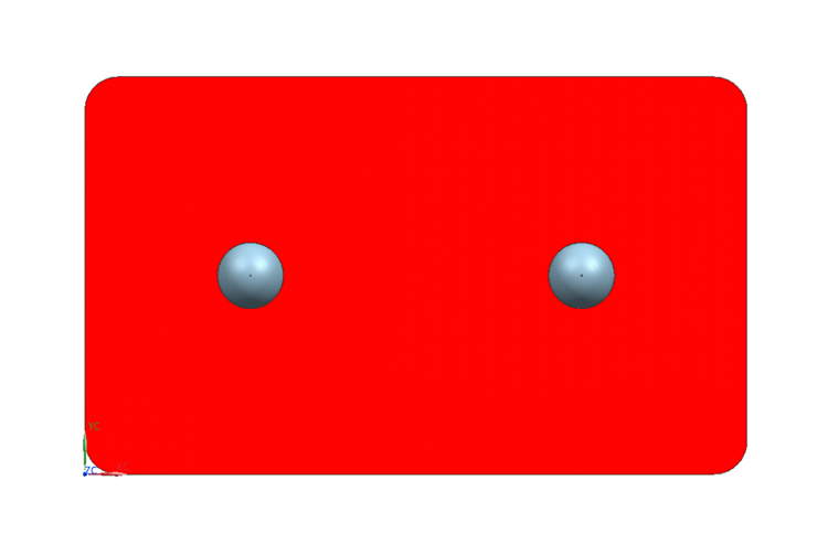
Figure 1. Which pin determines the X position of the workpiece? Impossible to determine.
The use of two pins placed in two holes poses problems in both location and manufacturing (Figure 1):
Problems with assembly
- Impossible to determine the exact location of workpieces.
- Creation of high stresses in the workpiece as a result of overconstraint in the workpiece location.
Problems with manufacturing
- Holes in the workpiece must be machined to very tight diameter and position tolerances, thus increasing the manufacturing cost.

Figure 2. The pin on the left determines the X position of the workpiece.
To overcome these issues, one of the pins can be assembled into a slot. Thus, the pin in the hole removes two translational degrees of freedom, while the one in the slot removes the final rotational degree of freedom.
In the next section, we will elaborate on the use of slots for overcoming the overconstraint problem through a sample part using geometric dimensioning and tolerancing principles defined by the ASME standard [1].
Use of Slots – A GD&T Example
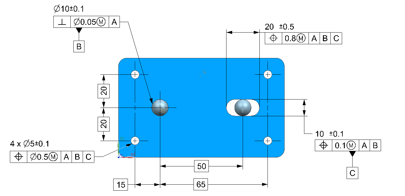
As we saw earlier, slots allow us to avoid overconstraint while having greater precision. An example of this can be seen in Figure 3.

Figure 3. Part with slot tolerances applied (Primary datum feature A is the flat plane at the bottom – Not Shown)
From Figure 3, we can observe the following:
- Primary datum feature (A): The flat plane at the bottom of the part (Not shown)
- Secondary datum feature (B): The hole defined with a feature size tolerance of ±0.1 mm and a perpendicularity tolerance of 0.05 mm at MMC with respect to the datum feature A.
- Tertiary datum feature (C): The width (vertical dimension) of the slot with a feature size tolerance of ±0.1 mm and a position tolerance of 0.1 mm at MMC with respect to datum reference frame AB.
- The length (horizontal dimension of the slot): This has a feature size tolerance of ±0.5 mm and a position tolerance of 0.8 mm at MMC with respect to datum reference frame ABC. Following the logic of using slots, this feature has the highest tolerances.
- The 4 hole pattern: The holes in the pattern have a feature size tolerance of ±0.1 mm and a position tolerance of 0.5 mm at MMC with respect to datum reference frame ABC. The position of these holes is defined using basic dimensions with respect to the datum reference frame ABC.
Despite the advantage of defeating the overconstraint, with slots we can still have the problem of high manufacturing cost if your part has substantial thickness. This is because manufacturing a slot is simply more complex than drilling a hole in relatively thick parts. One technique to have the best of the both worlds is to use diamond pins. We’ll explore this technique in a future post.
References:
ASME Y 14.5-2009, Dimensioning and Tolerancing. New York: American Society of Mechanical Engineers.